 |
 |
技術資料 »
Electrolytic Tilt Sensor Selection
& Operation
|
|
|

Download this document as a PDF file |
|
Description:
The function of an electrolytic tilt sensor is to measure an angle or a null or level position with reference to gravity. The angle may be expressed in any one of the following: degrees, arc minutes (1/60th of a degree), or arc seconds (1/60th of an arc minute). These angles are generally referenced to a perpendicular line to gravity called a null or zero point. The amount of tilt from this point can be expressed as either positive or negative angle.
A single axis sensor would only measure an angle in one direction. To measure an angle in all directions, for example, to a compass heading, a dual axis sensor or two single axis sensors mounted 90 degrees to each other would be required. This would allow the measurement to be made in any direction by combining the readings of both axes (see figure #1). The Fredericks Company manufactures all of these types of levels.
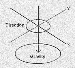
FIGURE #1 – Axes and direction
Selection:
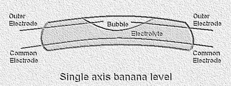
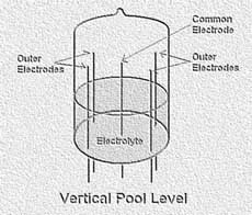
The selection of the proper sensor depends on the range of the angle being measured and the sensitivity required. If the measurement is to find a precise gravity reference for leveling sensitive instruments or equipment, a single axis horizontal vial (banana) type level would be used. These types of levels have sensitivities of less than an arc second with a range of a few degrees. For larger angle measurements, a vertical pool type level would be used. These types of levels can have a range of up to plus/minus 90 degrees or greater. They are available in single or dual axis.
Operation:
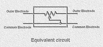
The electrolytic tilt sensor provides an output voltage that is proportional to the tilt angle. In a single axis level there are three electrodes, a common electrode and two outer electrodes. A dual axis level has five electrodes, a common and four outer electrodes. As the level is tilted, the fluid inside the level covers more or less of the outer electrodes depending on the direction of tilt. This causes the conductive path to present a ratio between the electrodes (see figure #2). It can be compared to a potentiometer with the wiper being the common electrode (see figure #3).
FIGURE #3 – Electrical equivalent
Operating parameters:
Electrolytic tilt sensors must be operated in the AC mode. Any direct current (DC) will cause the level to become unstable and even inoperable. The amount of current through the level must not exceed the maximum. Currents that are above the typical recommended value will cause the level to self heat and the readings will drift. The impedance value of the level must be specified to match the type of circuit used in order to limit the current.
Excitation:
The electrolytic tilt sensor (level) can be energized in a number of ways depending on the application and performance required. Typically, there are two ways to energize and read the level.
One way to energize the level is the use of a bridge type circuit (see figure #4). This configuration allows for the adjustment of the bridge resistors to match the internal impedance of the level. It must be noted that the electrolyte’s impedance will change with temperature. The impedance is inversely proportional to temperature. This can cause readings to change with temperature when the level is in an unbalanced position. Therefore, temperature compensation is required in an uncontrolled environment.
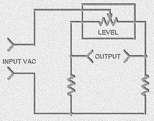
FIGURE #4 - AC bridge circuit
(Note: Additional circuitry is required to determine polarity of tilt)
Another way to energize the level is to excite the outer electrodes and read from the center (see figure #5). This method will ensure that only the ratio of the impedance is measured and not the absolute value of the impedance. The electrolyte’s impedance over the desired temperature range must not cause the current through the level to exceed the maximum value. Since the impedance is inversely proportional to temperature, an increase in temperature would cause an increase in current.
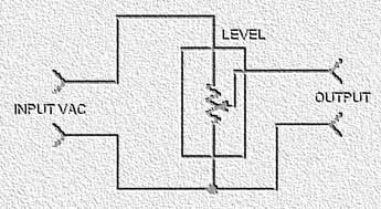
FIGURE #5 - AC exciting outer electrodes
(Note: Additional circuitry is required to determine polarity of tilt)
The output ports of a microcontroller are a good example of a drive circuit for the level, as long as each port exhibits equal source and sink currents thus preventing any DC component to the level. The output can be sampled between each port change by an analog to digital converter.
|
|
|
|
|
|
|
|
 |
|
|
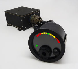 V-PRO車輛翻滾系統 - Early warning of LTV rollover risk, Visual and audible crew alerts, Simple 2-box solution » Read more V-PRO車輛翻滾系統 - Early warning of LTV rollover risk, Visual and audible crew alerts, Simple 2-box solution » Read more
|
|
|
|
 Mini Signal Conditioner Boards - Cost-effective & can be integrated into a larger system in a production environment. Easy way to evaluate tilt sensors. » Read more Mini Signal Conditioner Boards - Cost-effective & can be integrated into a larger system in a production environment. Easy way to evaluate tilt sensors. » Read more
|
|
|
|
 NEW Electrolytic Tilt Sensor with Patented Thin Film Technology - The sensor provides inclination measurement with arc second repeatability untouched by MEMS sensor technology. » Read more NEW Electrolytic Tilt Sensor with Patented Thin Film Technology - The sensor provides inclination measurement with arc second repeatability untouched by MEMS sensor technology. » Read more
|
|
|
|